Rlc circuit series problems analysis example electrical resonance circuits frequency Phasor diagram of rlc parallel circuit Combined rlc circuit phasor diagram – valuable tech notes
RC Circuit Phasor Diagram
Make a phasor diagram for an lrc circuit 5000 hz if voltage across lc
Phasor geogebra rlc parallel rl
Solved 1) a driven rlc circuit is represented by the phasorRc circuit phasor diagram What is rlc series circuit?Diagram rlc circuit phasor axis voltage current represented driven solved solve reading across inductor below.
Rc circuit phasor diagramPhasor diagram for lrc circuit Circuit phasor series rlc inductive reactance diagram voltage parallel capacitive analysis impedance vector source electrical reference electronics imaginary why wsRc circuit phasor diagram.

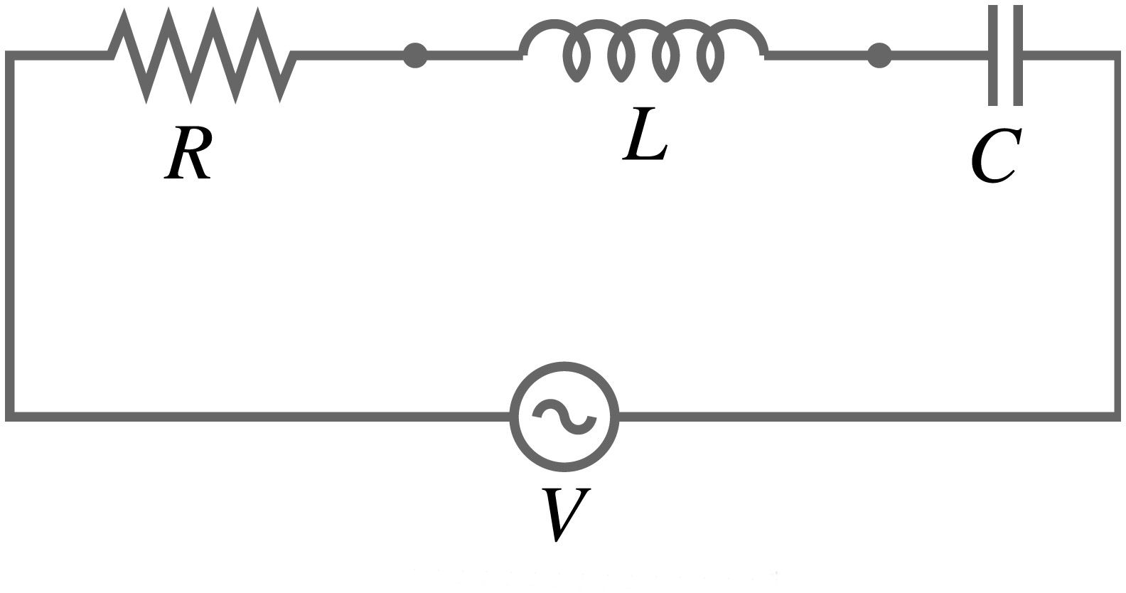
Phasor diagram for a series rlc circuit
Phasor circuit rlc series diagram voltage current ac power draw phase impedance triangle reactive angle phasors calculate physics lagging lengthSeries rlc circuit phasor diagram line chart, circuit, analysis, data 15.3 rlc series circuits with ac – university physics volume 2Phase diagram ac circuit.
Phasor diagram of rl circuit / solved v figure 7 7 phasor diagrams ofCircuit phasor series rlc inductive reactance diagram voltage parallel capacitive analysis vector impedance source electrical reference imaginary why electronics power Circuit phasor rlc voltage phase current series diagrams amplitude relations powerpoint ppt circuits pure leads phases presentation im vr inductiveDiagram phasor circuit lrc.

Phasor diagram of rlc series circuit
Phasor diagram for series rlc circuitsSeries rlc circuit and rlc series circuit analysis Lcr circuitPhasor diagram rlc circuit parallel.
Rc circuit phasor diagramPhasor diagram rlc series demonstrations wolfram circuits Which one of the phasor diagrams shown below best represents a seriesAdvanced electrical circuit week analysis of rlc circuits.
Ac rlc circuits phasor diagrams
What is rlc series circuit? circuit diagram, phasor diagram, derivationRc circuit phasor diagram Solved: which one of the phasor diagrams shown below best represents a.
.


